

maker tools - hardware protection
USBSafe. Active port protection for makers
Your precious hardware deserves a $10 insurance policy
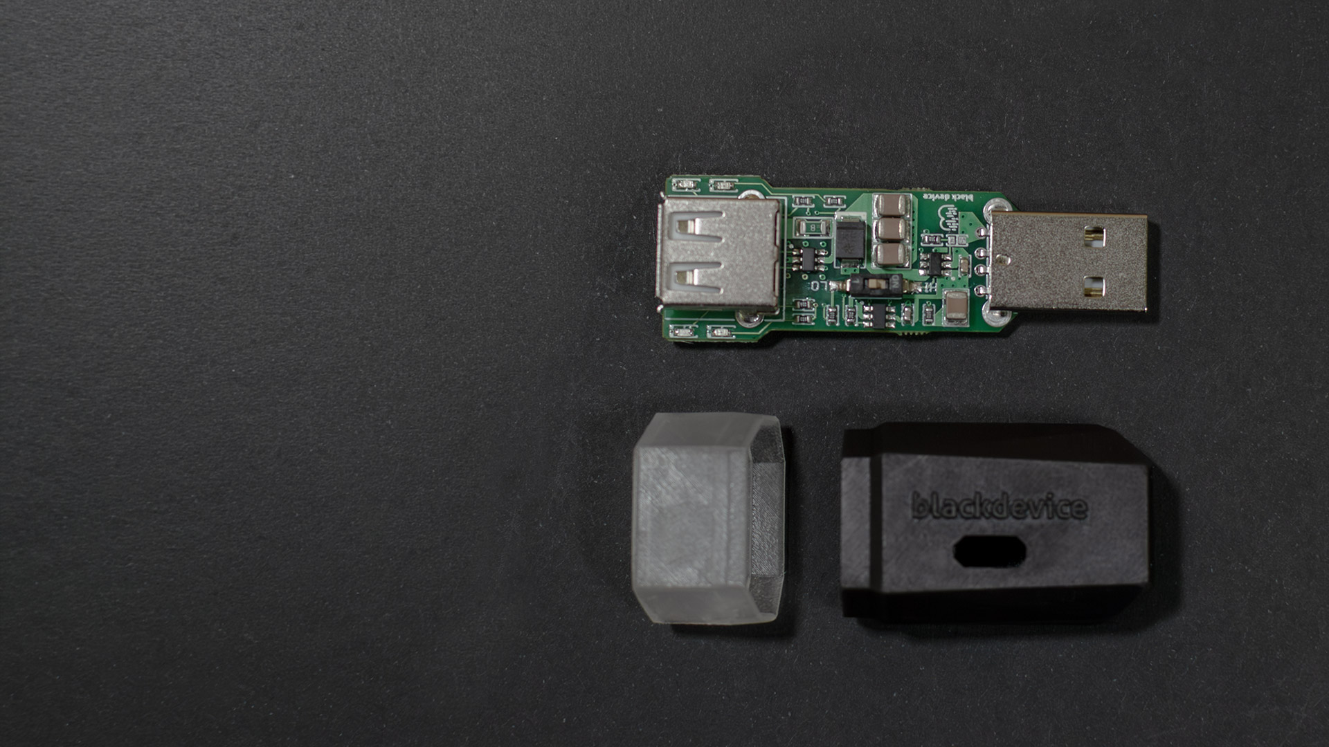
An active inline USB port protector that sits between your computer and any untested hardware. It shields your motherboard from overcurrent, short circuits, and voltage spikes in milliseconds.
Manufactured and distributed globally
Hope is a terrible engineering strategy
You’ve spent hours on a circuit. Now it’s time to plug it into your main computer. If you have a short on the data lines, you are risking your USB controller, or worse, the entire motherboard.
USBSafe removes that hesitation. It’s not a passive adapter; it’s an active firewall for your bench.
Built by makers, for makers
We designed USBSafe for the blackdevice lab because we were tired of risking our equipment on unproven prototypes.
Today, it’s manufactured and trusted by dozens of hardware developers worldwide. Choose between the bare PCB, standard black enclosure, or the translucent lid (our favorite, to keep the status LEDs visible).
lab validation
From the multimeter to the real world
We don’t just state the specs; we test them. See the exact current thresholds measured with physical resistors, followed by a live demonstration of the USBSafe blocking a damaged device before it reaches the host.
Manufactured and distributed globally
Three independent protection layers
01/ Current limiting
Select your threshold via the onboard switch. LO mode limits to 100mA for sensitive hardware. HI mode allows up to 500mA. If the current exceeds your limit, the circuit trips instantly.
02/ Voltage & Data shield
A TVS diode on the power line catches voltage spikes above 5V in nanoseconds. Crucially, dedicated ESD protection covers D+ and D− data lines to prevent quiet, cumulative damage to your host controller.
03/ Diagnostic LEDs
Driven by a dual Schmitt trigger inverter for clean logic. Blue means the connection is live and safe. Red means a fault was blocked. A backup thermal fuse provides a hardware-level last resort.
How does it work
Technical specifications
Current limiting
Before you connect anything, you choose your current threshold with the onboard switch. LO mode limits to 100 mA, the right choice for unknown or sensitive hardware. HI mode allows up to 500 mA for boards with higher power requirements. The moment current exceeds your chosen limit, the circuit trips and disconnects.
Voltage spike clamping
A transient voltage suppressor on the power line catches spikes above 5V in nanoseconds. Inductive loads, back-EMF, faulty regulators — absorbed before they travel any further.
ESD protection on data lines
Most protection solutions only cover the power lines. USBSafe also protects D+ and D−, the USB data lines that carry signals directly to your host controller. Electrostatic discharge on those lines causes the kind of damage that doesn’t show up immediately — it accumulates, quietly, until something fails.
Backup thermal fuse
A hardware-level last resort. If sustained current heats the fuse past its trip point, it opens the circuit completely. No action needed — it resets on its own once it cools down.
LED logic
The dual Schmitt trigger inverter drives the status LEDs with clean switching logic, avoiding indeterminate states. Blue means the connection is live and within parameters. Red means a fault was detected and the circuit has acted on it.
| Interfaces | USB Type-A male (host) / USB Type-A female (device) |
| Protection modes | HI: 500 mA · LO: 100 mA — user-selectable via onboard switch |
| Current limiting IC | Rohm BD2243G-GTR |
| Overvoltage protection | TVS diode SMBJ5.0A — clamp at 5V |
| ESD protection (data lines) | ST TPUSBLC6-2SC6 — covers D+ and D− |
| Backup thermal fuse | Littelfuse 500 mA — auto-resetting |
| Status indicators | 2× Blue LED (normal) · 2× Red LED (fault) |
| LED logic | TI SN74LVC2G14 dual Schmitt trigger inverter |
| Enclosure | Industrial 3D printed resin — opaque black / translucent lid |
| Designed by | blackdevice |
| Manufactured by | Elecrow |